![]() Another splended and helpful page from dodge50.co.uk
Another splended and helpful page from dodge50.co.uk
DESCRIPTION AND MODIFICATIONS
AIR / HYDRAULIC SYSTEM Description
Compressed air is supplied to a tandem actuator which in turn operates a tandem
hydraulic master cylinder. The air system- is split. and each section is supplied
with air by separate reservoirs. The hydraulic circuit is also split, the separate
chambers of the master cylinder each operating the brake units on one axle.
In this system failure of one part of the air system allows reduced but effective
braking on both axles, whilst a failure of one part of the hydraulic system
provides full braking on one axle.
The secondary brake is considered to be the unfailed part of the system.
The hand control valve on this system provides park braking. Exhausting air
from a single spring brake unit on the rear axle releases a powerful spring
to operate the brake units mechanically through a compensator linkage.
Brake Assemblies
Front brakes are of two leading shoe design and incorporate a self adjusting
mechanism mounted on each shoe. Two single acting cylinders are fitted to each
assembly.
Rear brakes of the duo-servo type are each fitted with a single double acting
cylinder and the automatic adjuster, which is floating, fits between the
two shoe webs.
Both types of adjuster have the facility
for manually de-adjusting to assist brake drum removal.
Air System
Air is supplied by a compressor,
belt driven on the 6.247 engine and gear driven on the 4.236 engine.
The system incorporates a dual air gauge, a low air pressure warning switch
fitted to each service reservoir operating a warning buzzer in the cab. A low
air pressure warning switch fitted in the park brake circuit operates a warning
light on the instrument panel.
Hydraulic System
The tandem master cylinder with its direct mounted fluid reservoir is split
vertically, the primary cylinder operates the front brakes and the secondary
cylinder operates the rear brakes.
A low fluid level indicator is located in the reservoir cap and this has the facility for manually testing its integrity. The integrity of the low fluid level warning light, mounted on the instrument panel, is checked each time a cab door is opened.
Rear wheel braking is controlled
by a load sensing valve mounted on the rear axle.
The setting instructions for this valve are extremely important.
Key Below
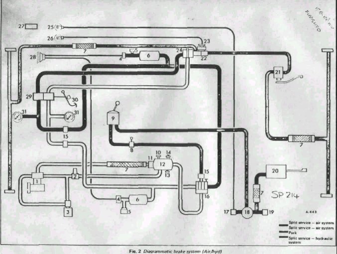
Key to Fig. 2 DIAGRAMATIC BRAKE SYSTEM AIR / HYDRAULIC- HAULAGE Mk 1
Dodge 50
1.COMPRESSOR
2. GOVERNOR VALVE
3. ANTI-FREEZE EQUIPMENT - WHEN FITTED
4. LOW PRESSURE WARNING
5. SWITCH TEST POINT
6. SERVICE RESERVOIR
7. FLEXIBLE HOSE
8. AUTO RELEASE VALVE - WHEN FITTED
9. PARKING BRAKE CONTROL VALVE
10. SAFETY VALVE
11. NON.RETURN VALVE
12. SENSING RESERVOIR
13. AUTOMATIC DRAIN VALVE
14 SCHRADER VALVE
15. FILTER
16. QUADRUPLE PROTECTION VALVE
17. LOW PRESSURE WARNING SWITCH
18. QUICK RELEASE VALVE
19. STOP LIGHT SWITCH
20. SPRING BRAKE
21. LOAD SENSING VALVE
22. TANDEM MASTER CYLINDER
23. FLUID LEVEL SWITCH
24. TANDEM ACTUATOR
25. SPRING BRAKE WARNING LIGHT
26. FLUID LEVELWARNING LIGHT
27. INSTRUCTION PLATE - LOAD SENSING VALVE
28. LOW PRESSURE WARNING BUZZER :
29. FOOT CONTROL VALVE
30. STOP LIGHT SWITCH
31. AIR GAUGE
Mk 2 Dodge 50 Diagramatic and Key Below
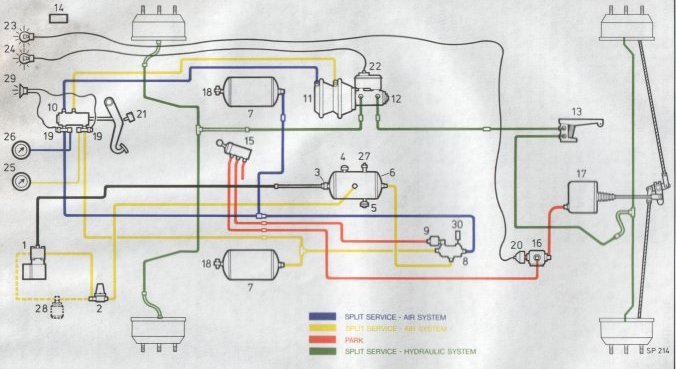
Key to Fig. 2 DIAGRAMATIC BRAKE SYSTEM AIR / HYDRAULIC- HAULAGE
1.COMPRESSOR
2. GOVERNOR VALVE
3. NON-RETURN VALVE
4. SAFETY VALVE
5. AUTOMATIC DRAIN VALVE
6. SENSING RESERVOIR
7. SERVICE RESERVOIR
8. QUADRUPLE PROTECTION VALVE
9. FILTER
10. DUEL BRAKE VALVE
11. TANDEM ACTUATOR
12. VENTED TANDEM MASTER CYLINDER
13. LOAD SENSING VALVE
14. INSTRUCTION PLATE - LOAD SENSING VALVE
15. HAND CONTROL VALVE
16. QUICK RELEASE VALVE
17. SPRING BRAKE
18. TEST POINT
19. LOW PRESSURE WARNING SWITCH
20. LOW PRESSURE WARNING SWITCH
21. STOP LIGHT SWITCH
22. FLUID LEVEL INDICATOR
23.SPRING BRAKE WARNING LIGHT FLUID LEVEL SWITCH
24. FLUID LEVELWARNING LIGHT
25. AIR GAUGE 1
26. AIR GAUGE 2
27. SCHRADER VALVE
28. ANTI-FREEZE (OPTIONAL)
29. LOW PRESSURE WARNING BUZZER
30. MANIFOLD BLOCK FOR AUXILIRARY EQUIPMENT
©
Dodge50.co.uk™
2002