![]() Another splended and helpful page from dodge50.co.uk
Another splended and helpful page from dodge50.co.uk

•>For CHASSIS No. 219001onwards
BRAKES Description
AIR/HYDRAULIC SYSTEM — P.S.V.
The service system consists of a tandem actuator unit supplying hydraulic pressure to all brakes. Both air and hydraulic systems are split. The secondary brake is the unfailed half of either the air or the hydraulic system. On P.S.V. models a Telma retarder assists the service brake.
Brake Fluid Low Level Warning System
To check the low level warning light bulb, open the cab door and the warning light will illuminate. To check the operation of the low level warning switch, ensure that the cab interior lamps are switched to the .courtesy position, i.e. lamp only lights when doors are open. Close both doors. Unscrew the filler caps one at a time and lift. As the float falls the switch will make contact and the interior lamp will light.
Parking is by a spring brake unit mounted on the rear axle being operated by
a hand control valve at the side of the drivers seat.
Air System
Compressed air is supplied by an engine mounted compressor gear driven from the rear of the timing case. The air is fed to a sensing reservoir in which the pressure is monitored and regulated by a governor valve. The sensing reservoir supplies two independant service reservoirs which then separately supply the two inlet ports of the dual brake pedal valve. Air pressure relative to the dnver's effort on the brake pedal is fed to the tandem actuator. The tandem actuator is fitted to the back of the tandem master cylinder.
Brake Assemblies
The front brakes are two leading shoe and are manually adjusted. The rear brakes are duo servo and are self adjusting. The rear brakes have a manual override facility for initial adjustment and to assist in drum removal.
Parking Brake
The parking brake is operated by a hand control valve in the cab. With the valve in the 'OFF' position, air under pressure is compressing a spring. Application of the valve to the 'ON' position dumps air to atmosphere allowing the spring to expand and apply the rear brakes mechanically through the compensator mechanism.
If a failure occurs in one half of
the air system, the other half will provide reduced but effective braking on
both axles.
Hydraulic System — 6mm diameter steel tubing transfers the hydraulic pressure
generated in the master cyclinder to the brake assemblies. The primary cylinder
operates the front brakes and the secondary cylinder the rear brakes. Each cylinder
is supplied by its own fluid reservoir. Each reservoir has a low fluid
level switch which operates a warning light when the brake fluid reaches a minimum
level.
PUBLIC SERVICE VEHICLES
These vehicles are fitted with a Telma retarder. The retarder is controlled by pressure switches which are sensed by the pressure advance in the outlet side of the foot brake valve. The brake system is designed so that the retarder operates first followed by the normal service brake. This is achieved by the front and rear hydraulic circuits being fitted with delay valves. The delay valves do not open until a pressure of 1 2,4 bar (1 80 p.s.i.) is reached. The retarder will cover most of the "check" braking. During normal brake application the delay in the service brake will not be apparent.
If a failure occurs in one half of the hydraulic system, full braking effort
is still available on one axle.
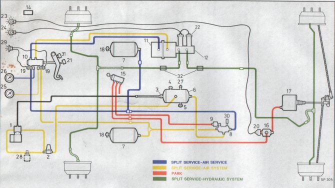
Key to Fig. 2 DIAGRAMATIC BRAKE SYSTEM AIR / HYDRAULIC- P.S.V.
1.COMPRESSOR
2. GOVERNOR VALVE
3. NON-RETURN VALVE
4. SAFETY VALVE
5. AUTOMATIC DRAIN VALVE
6. SENSING RESERVOIR
7. SERVICE RESERVOIR
8. QUADRUPLE PROTECTION VALVE
9. FILTER
10. DUEL BRAKE VALVE
11. TANDEM ACTUATOR
12. VENTED TANDEM MASTER CYLINDER
13. Not Allocated
14. INSTRUCTION PLATE - LOAD SENSING VALVE
15. HAND CONTROL VALVE
16. QUICK RELEASE VALVE
17. SPRING BRAKE
18. TEST POINT
19. LOW PRESSURE WARNING SWITCH
20. LOW PRESSURE WARNING SWITCH
21. STOP LIGHT SWITCH
22. FLUID LEVEL INDICATOR
23. SPRING BRAKE WARNING LIGHT FLUID LEVEL SWITCH
24. FLUID LEVELWARNING LIGHT
25. AIR GAUGE 1
26. AIR GAUGE 2
27. SCHRADER VALVE
28. ANTI-FREEZE (OPTIONAL)
29. LOW PRESSURE WARNING BUZZER
30. MANIFOLD BLOCK FOR AUXILIRARY EQUIPMENT
31. RETARDER CONTROL SWITCH
32. DELAY VALVE
© Dodge50.co.uk™ 2002