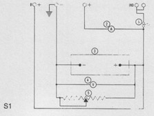
Fig. S.1. illustrates
a Test Circuit for 15ACR and
17ACR alternators with standard terminations, battery-
sensed.
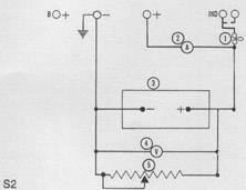
Fig. S.2. illustrates a Test Circuit for 15ACR and 17ACR
alternators with standard terminals and two piece con-
nection plug (machine-sensed).
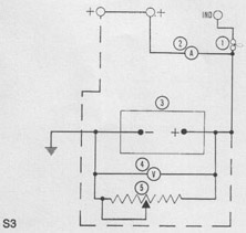
Fig. S.3 illustrates a Test Circuit for 15ACR, 17ACR, 18ACR,
23ACR, A115/45. A127. A133/55 and LR series alternators
with European terminations and single 3 terminal connector
plug (machine-sensed). Broken line cable connection applies
to battery-sensed, in which case, the connections between
the two • + ' terminals will not apply and the broken line ter-
minal will be marked "S" instead of ' + '.
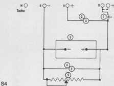
S.4 shows a test circuit for Motorola 9AR.
Value of components in Figs. S.1, S.2, S.3 and S.4 are as
follows:-
1. 12 volt 2.2 watt bulb.
2. 0 - 60 ammeter
3. 12 volt battery
4. 0 - 20 moving coil voltmeter.
5. C - 1 5 o^t 50 amp variable resistor.
Alternator Output Test with Regulator Inoperative
Withd-aw the cable connector(s) from the alternator.
remo'.e the moulded cover (secured by two screws)
and earth the regulator green lead or connector strip
tc 'rare.
Connect an external test circuit to the alternator output
terminals as shown in Figs. S.1, S.2, S.3 or S.4.
Observe carefully the polarity of battery and alternator
terminals - reversed connections will damage the
alternator diodes.
The variab!e resistor across the battery terminals must
not be left connected for longer than is necessary to
carry out the following test.
Start the engine. At 1,500 rev/min (alternator speed).
the test circuit bulb should be extinguished. Increase
engine speed until the alternator is running at 6,000
rev/m;n approximately, and adjust the variable resist-
ance until the voltmeter reads 13.6 volts. The ammeter
reading should then be approximately equal to the
rated output (see previous heading). Any appreciable
deviation from this figure will necessitate the alternator
being removed from the engine for further examination.
Failure of one or more of the diodes will be indicated
in the above test by effect on alternator output, and
also in some instances by abnormally high alternator
temperature and noise level.
Regulator Test
The following test assumes the alternator to have been
tested and found satisfactory.
Disconnect the variable resistor and remove the earth
connection from the regulator green lead or connector
strip to frame.
With the remainder of the test circuit connected as for
the alternator output test, start the engine and again
run the alternator up to 6,000 rev/min until the ammeter
shows an output current of less than 10 amperes. The
voltmeter should then give a reading of 13.6 - 14.4
volts. Any appreciable deviation from this (regulating)
voltage means that the regulator is not functioning properly
and must be replaced.
If the foregoing tests show the alternator and regulator
to be satisfactorily performing, disconnect the test
circuit and reconnect the alternator terminal connector.
Now connect a low range voltmeter between the posi-
tive terminal of the alternator (the moulded terminal
connector is open ended to facilitate this) and the
positive terminal of the battery. Switch on battery load
(headlights etc.), start the engine and increase speed
until the alternator runs at approximately 6,000 rev/min.
Note the voltmeter reading.
Transfer the voltmeter connections to the negative
terminals of the alternator and battery and again note
the meter reading.
If the reading exceeds 0.5 volt on the positive side or
0.25 volt on the negative side, there is a high resistance
in the charging circuit which must be traced and remedied.
© Dodge50.co.uk™ 2002