Another splended and helpful page from dodge50.co.uk©
|
|
 |
Steering
Box To Remove Disconnect battery. Remove the engine sound insulation panel immediately to the rear of the steering box to allow access to the steering box securing nuts. Open and secure bonnet. Remove the
pinch bolt and nut securing the universal joint to the steering
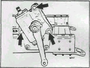
box splined input shaft. Chock the rear wheels and ensure that the parking brake is applied. Slacken the nuts of the wheel adjacent to the steering box. Support the steering box and remove the three nuts and bolts securing it to the mounting bracket. Disengage the splined input shaft from the universal joint and remove the steering box. Raise the vehicle until both front wheels are clear of the ground. Position suitable supports to permit safe access to the steering gear. Remove the road wheel adjacent to the steering box.
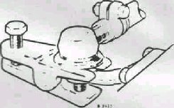
Position the steering wheel in the 'Straight Ahead' position, i.e. with the spokes in the 'twenty minutes to four' position. Remove split pin and nut securing the forward ball joint of the side steering rod to the drop arm. Using Tool 18G 1133. release the joint from the drop arm. Engage the input shaft and universal joint splines, position the steering box in its mounting bracket, fit the securing bolts and nuts and tighten to a torque of 92 Nm (68 Ibf ft). Steering Box Insert the pinch bolt and nut into the universal joint assembly noting that the bolt passes through the relieved portion of the input shaft. Tighten to a torque of 26 Nm (19 Ibf ft) Adjust the steering stops Fit the engine sound insulation panel. Check that the steering wheel is correctly positioned with the road wheels in the 'Straight Ahead' position. If mis-aligned, reposition as necessary. Position the forward ball Joint of the side steering rod in its location on the drop arm. Fit the nut and tighten to a torque of 95 Nm (70 Ibf ft). Fit a new split pin and bend back the legs. If the nut does not align with the drilling, tighten the nut just enough to allow the pin to be inserted. Do NOT slacken the nut to allow insertion of the pin. Remove the
combined oil filler/level plug and check oil level. Top-up as necessary
and refit Plug- Close the bonnet.
Fig. 1 Steering box and mourning bracket. Fig.2 Releasing ball joint using Tool 18G 1133 |
|
|
 Dodge
50 Series Workshop Manual
Dodge
50 Series Workshop Manual