 Dodge
50 Series Workshop Manual Dodge
50 Series Workshop Manual
A440
Page's 6 & 7
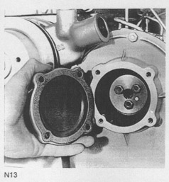
3. Remove
the timing case front cover inspection
plate (Fig. N.13).
4. Remove the three setscrews or nut which secure
the fuel pump gear to the fuel pump.
5. Remove the fuel pump from the timing case ensur-
ing that when the fuel pump gear leaves the shaft
it stays in mesh with the idler gear otherwise the
fuel pump timing will be affected
To Refit the Fuel Pump
(Mechanical Governor)
1. Replace the fuel pump ensuring that the slot, or key
in the pump hub, or shaft is aligned with the dowel
(or keyway) in the gear.
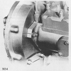
2. Position the pump so that the scribed line on the
pump flange aligns with the mark on the timing
case (Fig. N.14). Secure the pump to the timing
case. To check accuracy of mark on rear of
timing case. this may be ascertained in accordance
with the instructions for marking a new timing case.
3. Secure
the driving gear to the fuel pump shaft with
tne tn'ee setscrews and spring washers, or nut
ensuring the dowel or keyway is properly located in
us slot.
4. Fit the timing case inspection cover.
5. Refit the low and high pressure pipes to the fuel
pump,
6. Re-connect the throttle and stop lever controls and
attach the return springs.
7. Vent the air from the fuel system .
8. Adjust the maximum and idling speeds,
NOTE; Where a fuel pump rear support bracket is fitted,
ensure that when the fasteners are tightened the pump
or bracket are not stressed.
Fuel Pump Gear
To Re-set the Fuel Pump Timing - D.P.A.
On the fuel pump rotor, inside the fuel pump are a
number of scribed lines, each one bearing an indi-
vidual letter. A timing circlip is positioned inside the N14
pump and has to be set so that when the appropriate
scribed line on the fuel pump rotor aligns with the
scribed line on the circlip, it denotes
commencement of injection (static timing).
NOTE: On later engines
the scribed line on the circlip
has been deleted. On these engines the scribed line on
the rotor should be aligned with the end of the circlip
which has the straight edge. The circlip on
current pumps is not set and timing tool MS67B must
be used.
To set the
timing circlip, it is necessary to remove the
pump from the engine and fix the position of the circlip
by connecting No. 1 cylinder outlet connection (marked
"W") to an atomiser tester and pump up to 30 atm
(31 kgf/cm' or 440 Ibf/in2).
Turn the
pump by hand in
the normal direction of rotation until it "locks up".
The squared end of the circlip should now be adjusted
until it lines up with the letter "A" for hydraulic pumps
or the letter "C" for mechanical pumps, on the pump rotor.
To re-set the fuel timing the following procedure 5.
should be adopted:-
a)
Hydraulically Governed Pump
Ensure that the fuel pump circlip is correctly positioned
as described previously.
1. Ensure that the fuel pump is correctly fitted with
the scribed line on the mounting flange aligning
with the mark on the fuel pump gear carrier (Fig.
N.12).
2. Position the crankshaft so that No. 1 piston is at
T.D.C. on compression stroke.
3. Remove the collets, spring cap and spring from the
inlet valve of No. 1 cylinder and allow the valve to
rest on the top of the piston.
4. With the aid of a clock gauge in contact with the
end of the valve now resting on the No. 1 piston
it will be necessary to position the crankshaft at
the static timing position.
5. Remove the inspection plate on the fuel pump en-
abling the rotor to be seen.
|