 Dodge
50 Series Workshop Manual Dodge
50 Series Workshop Manual
A440
Page's 7 & 8
6. With
No. 1 piston at the static timing point on its
compression stroke, the scribed line on the fuel
pump rotor marked "A" should align with the
scribed line or straight edge on the circlip.
If it does
not, release the fuel
pump drive plate securing setscrews and turn the
drive plate on the slotted holes, the required
amount to bring them into alignment. Access to
the drive plate is gained by removing the timing
case front cover inspection plate
7. When the fuel pump timing is correct, obliterate
the mark on the fuel pump drive gear and re-mark
the gear to correspond with the mark on the fuel
pump drive plate
8. Refit the spring, spring cap and collets to No. 1
inlet valve and refit the pump inspection plate and
timing case inspection plate.Re-seal
the inspection plate.
(b) Mechanically Governed Pumps- D.P.A.
The procedure for re-setting the fuel pump timing on
mechanically governed engines is similar to that used
for hydraulically governed engines with the exception
of the method of pump adjustment.
As there is no adjustable fuel pump drive plate on a
mechanically governed engine, the adjustment is carried
out by slackening the nuts on the pump mounting flange
and rotating the pump body until the scribed line on the
rotor, marked with the letter 'C' aligns with the scribed
line or straight edge of the circlip.
The circlip on current pumps is not set and timing tool
MS67B must be used.
To Check Marking Angle of Fuel Injection
Pump using Tool MS.67B
- D.P.A./D.P.S. Pumps
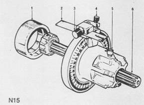
1. Release screw (5, Fig. N.15) and remove splined
shaft (6). If pump has a slotted hub, the splined
shaft should be retained with the small -r ihed
diameter to the rear to locate in the centre of the
hub.
2. Ensure that slotted pointer (2) is positioned with
slot to rear of tool and chamfered sides of slot
outwards. At this stage, slotted end of pointer
should be kept well back towards body of tool.
Ensure that the flat in the washer fitted behind the
pointer securing screw (3) is located over side of
pointer.
3. Release bracket screw (4) and set bracket so that
the chamfered edge is in line with the relevant
marking angle.
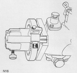
4. Position timing tool on pump drive shaft with master
splines engaged and tool locating on spigot (see
Fig. N.16). For D.P.S. pumps, first fit adaptor PD67-3
to end of pump drive shaft, (see Fig. N.16A). With
dowel drive pumps, locate splined shaft in hub, slide
tool towards pump to rest on end of hub and lock
shaft in tool (See Fig. N17).
5. Connect No. 1 outlet of pump body to an atomiser
test rig and pump up to 30 atmospheres (31
kgf/cm-') -440 Ibf/in2. If pressurising valve is
fitted this must be removed.
6. Turn pump in normal direction of rotation as shown
on pump nameplate, until it locks.
N16A
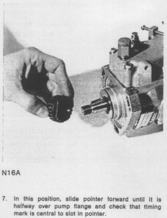
7. In this position, slide pointer forward until it is
halfway over pump flange and check that timing
mark is central to slot in pointer.
|