 Dodge
50 Series Workshop Manual Dodge
50 Series Workshop Manual
A440
Page's 8 & 9
When fitting
a replacement fuel pump, or in the event of
the maximum
speed screw having been moved, the max-
imum no load speed must be checked and re-set as
necessary.
The maximum no load speed will vary according to
application. For details, reference should be made to
the code number stamped on the fuel pump data plate.
The last four numbers in the code indicate the speed
required, and in the case of the example on page N10,
this would be 3130 rev/min.
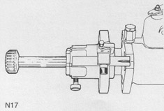
To Check Marking Angle of Fuel Injection Pump
using Tool MS. 67B and adaptors PD.67B-1 and
PD. 678-6 (Stanadyne Pump)
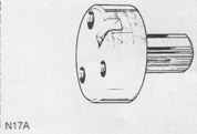
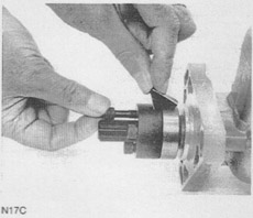
1. Fit the adaptor PD.67B-1 (Fig. N17A) to the hub of
the pJms by use of the special setscrews, part of
tool PD.67B-6 (Fig. N17C). Ensure that the location
slots of the hub and adaptor are together and in line
(use the alignment gauge, part of tool PD.67-6) and
that the adaptor is concentric with the hub.
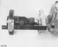
2. Remove the splined shaft from the timing tool
MS.67B (6. Fig. N15) and slide the small splined
open end of the timing tool onto the splined shaft of
adaptor PD.67B-1 (Fig, N17D). Lock the timing tool
into position with the securing screw (5, Fig. N15).
3. Ensure the long pointer, part of tool PD.67B-6 is in
position and that the sides of the slot with chamfers
are on the outside. Ensure that the flat of the
washer fitted behind the screw (3, Fig. N15) which
fastens the pointer is in position.
4. Release the screw (4, Fig. N15) which fastens the
bracket and set the bracket so that the edge with a
chamfer is in line with the correct fuel injection
pump mark angle.
Note: As the tool will have to be fitted in the reverse
position to normal; the setting angle has been
adjusted to allow for this.
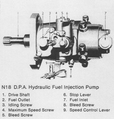
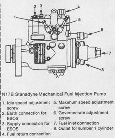
5. Connect No. 1 cylinder outlet (8, Fig. N17B) to an
atomiser tester and operate the tester until it
reaches 31 kgf/cm2 (30 atm or 440 Ibf/in2). If a
pressure vaive is fitted, this must be removed.
6. Turn the drive shaft of the pump backwards and
forwards until the fuel pressure prevents movement
of the shaft. This is necessary as fuel must pass the
delivery valve in the fuel pump before the fuel
pressure will prevent movement of the shaft. In this
position, the fuel pump is set at the start of ignition
from number 1 outlet.
7. Move the pointer forward until it is half over the
pump flange. Check that the timing mark is central
to the slot in the pointer. Make a new timing mark if
necessary.
©
Dodge50.co.uk™
2002 |